|
Connecting to Hardware Using OpenOCDGDB is an open-source debugger, part of the GNU project. GDB defines a serial protocol, more often used on TCP/IP than on actual serial connections, to permit remote debugging. NoICE can use this protocol to debug ARM targets. (Note that NoICE does not use GDB or any GDB code - only the GDB protocol in order to communicate with a target.) OpenOCD (http://developer.berlios.de/projects/openocd) is a free, open-source program that implements both a GDB server and a simple TTY (via TELNET) interface to ARM JTAG. It supports a number of JTAG interface pods including:
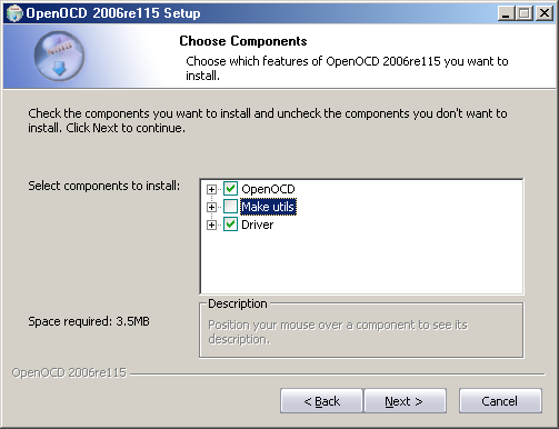
In the section of the tutorial, we will show how to use OpenOCD as a GDB server in order to connect the Olimex ARM-USB-OCD and Wiggler clone pods to an LPC2106 target. Our target board is the Olimex LPC-P2106-B. If you haven't done so already, we recommend that you go through Running NoICE for the first time before reading this section of the tutorial. Click here for a tutorial on connecting to hardware using the Segger JLink. Click here for a tutorial on connecting to hardware using H-JTAG (supports the Macraigor Wiggler and clones) Obtaining and Installing OpenOCD and DriversIf you are familiar with Cygwin, you can download the OpenOCD source code from http://developer.berlios.de/projects/openocd and build it yourself. However, most users will find it simpler to download a pre-built version of OpenOCD from YAGARTO (Yet Another GNU ARM Toolchain) at http://www.yagarto.de. Download "Open On-Chip Debugger" (and the GNU toolchain and Eclipse IDE if you want them). Complete instructions for OpenOCD are at http://www.yagarto.de/howto/openocd/index.html. For our purposes, you will need to install at least OpenOCD and the drivers.
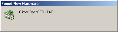
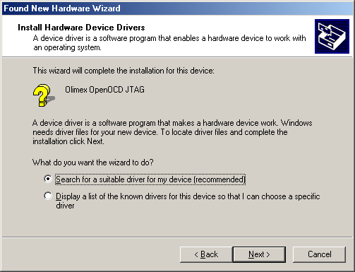
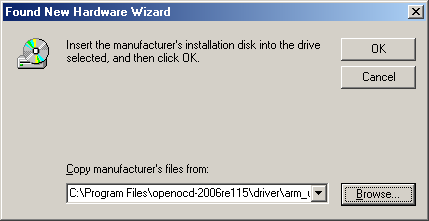
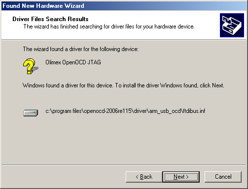
Click here if you are using the Olimex ARM-USB-OCD JTAG Pod Click here if you are using a Macraigor Wiggler or Wiggler clone JTAG Pod Connecting the Olimex ARM-USB-OCD JTAG Pod
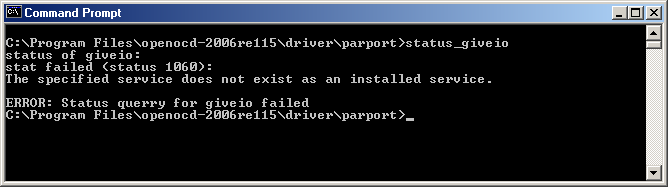
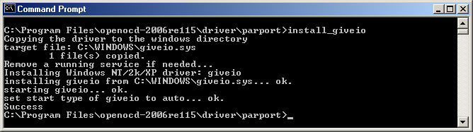
Connecting a Macraigor Wiggler or Wiggler clone JTAG PodYagarto OpenOCD uses the giveio driver to provide program access to the parallel port. The following steps must be performed with administrator rights. Go to a command prompt, and navigate to the "parport" directory under wherever you installed OpenOCD - usually something like C:\Program Files\openocd-2006re115\driver\parport You should see three batch files: install_giveio.bat, remove_giveio.bat, and status_giveio.bat.
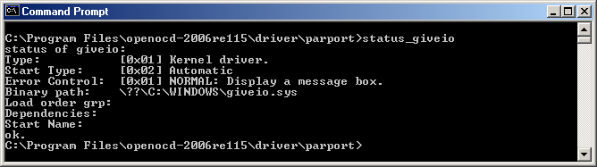
This procedure only needs to be done once. On subsequent reboots, giveio.sys will be restarted automatically. You are now ready to connect the Wiggler to your target hardware (administrator rights not required)
Running OpenOCDBefore you can run NoICE, you must run OpenOCD as a GDB server. If you installed the Yagarto version of OpenOCD, look in the "bin" directory under wherever you installed OpenOCD, usually something like C:\Program Files\openocd-2006re115\bin You should see two files,
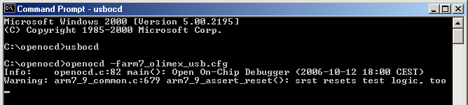
OpenOCD must be run with a configuration file to specify various target options. To use the Olimex ARM-USB-OCD we run openocd-ftd2xx -farm7_olimex_usb.cfg where the file arm7_olimex_usb.cfg contains: #daemon configuration telnet_port 4444 gdb_port 3333 #interface interface ft2232 ft2232_device_desc "Olimex OpenOCD JTAG A" ft2232_layout olimex-jtag ft2232_vid_pid 0x15ba 0x0003 jtag_speed 3 #use combined on interfaces or targets that can't set TRST/SRST separately reset_config trst_and_srst srst_pulls_trst #jtag scan chain #format L IRC IRCM IDCODE (Length, IR Capture, IR Capture Mask, IDCODE) jtag_device 4 0x1 0xf 0xe #target configuration daemon_startup reset #target <type> <startup mode> #target arm7tdmi <reset mode> <chainpos> <endianness> <variant> target arm7tdmi little run_and_halt 0 arm7tdmi-s_r4 run_and_halt_time 0 30 Additional sample cfg files may be found in the OpenOCD bin\configs subdirectory. Running openocd-ftd2xx should result in output something like this
If you have problems, more information configuration options, and a variety of sample configuration files are available from OpenOCD and YAGARTO Once OpenOCD is up and running, you can run NoICE To use the Olimex Wiggler clone we would run openocd-pp -farm7_wig.cfg where the file arm7_wig.cfg contains: #daemon configuration telnet_port 4444 gdb_port 3333 #interface interface parport parport_port 0x378 parport_cable wiggler jtag_speed 0 #use combined on interfaces or targets that can't set TRST/SRST separately reset_config trst_and_srst srst_pulls_trst #jtag scan chain #format L IRC IRCM IDCODE (Length, IR Capture, IR Capture Mask, IDCODE) jtag_device 4 0x1 0xf 0xe #target configuration daemon_startup reset #target <type> <startup mode> #target arm7tdmi <reset mode> <chainpos> <endianness> <variant> target arm7tdmi little run_and_halt 0 arm7tdmi-s_r4 run_and_halt_time 0 200 Running openocd-pp should result in output similar to that shown above. Once OpenOCD is up and running, you can run NoICE Running NoICE
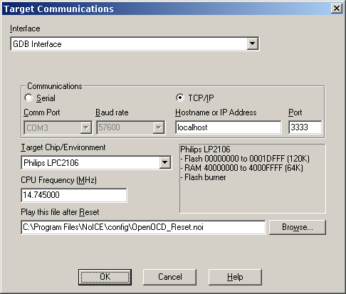
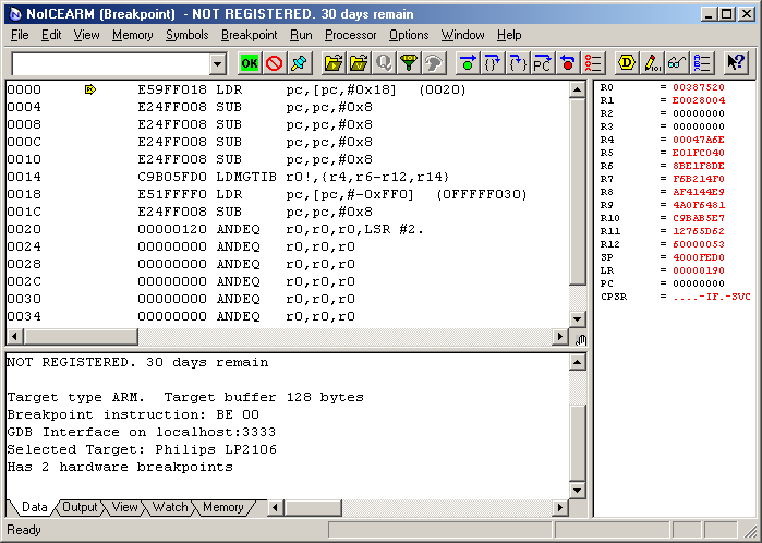
A Digression on ARM ResetSome ARM vendors have decided to make life difficult by quirks in the reset handling of their ARM processors. In particular, Philips (which makes some lovely inexpensive processors with wonderful peripherals) has a bootloader that takes control after reset. It computes a checksum on the ARM interrupt vectors. Only if the checksum is deemed correct will control be passed to the Flash reset vector. If the checksum isn't correct, the boot loader remains is control, and may be seen by NoICE. However, the boot loader scheme means that the only way JTAG can "reset" a Philips LPC2xxx is to reset it, let it run long enough for the boot loader to do its stuff, and then stop the program. Unfortunately, at the time of stop there is no telling what the states of the various peripherals are, whether RAM or Flash or the boot loader mapped at location zero, etc. OpenOCD does not implement the GDB reset message. The GDB protocol document deprecates the reset message, so OpenOCD is certainly "legal", but reset is a very useful message for embedded debugging. In order to get a reliable reset of your target in the absence of GDB reset, we recommend that you specify a Play After Reset command file with content similar to the following: ECHO Send OpenOCD commands to reset a Philips LPC21xx RCMD reset run_and_halt ; OpenOCD reset may take a while, so give it time to complete WAIT 500 ; "run_and_halt" leaves the PC in the boot ROM. Fake a "textbook" reset. RCMD soft_reset_halt ; If you want to use software breakpoints for programs in RAM, change ; the final parameter in the following RCMD command from "disable" to ; "enable. This will leave you only one hardware breakpoint, so do ; this ONLY if you need to use software breakpoints. RCMD arm7_9 sw_bkpt disable A file called OpenOCD_Reset.noi containing this content will be installed in your NoICE\config directory. Press "OK" in the Target Communications dialog, and NoICE will show an initial
display like that shown below. If you exit NoICE and come back in, you will
return right here.
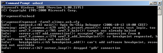
In this case, memory contains a previously-burned program. Since the ARM begins execution at address 0, that is where PC starts out. NoICE disassembles from the PC. One restriction on the GDB protocol is that it does not provide access to the ARM's banked or shadow registers. You can see R0 through R15 and CPSR for the current mode, but the SPSR and registers for other modes are not visible as they are when you use the simulator, JLink, or RDI interfaces. At this point, you may wish to repeat the simulator examples on real hardware. If you look at OpenOCD's output window, you will see something like this
Don't worry about the warning messages: when NoICE starts up, it sends various commands to the GDB server in order to determine what features are available. If OpenOCD doesn't support a command, it may issue a warning output. The next step is to burn a program into Flash. This example uses ImageCraft ICCARM, as described in the previous section of the tutorial, Compiling for Source-level Debugging. You can follow along even if you don't have this compiler. All files necessary for you to run the NoICE demo may be downloaded here: hellofoo.zip. Setup for other compilers is generally similar.
Once burning is completed, you can continue with the source-level debugging example |