Connecting to Hardware Using H-JTAG
H-JTAG (http://hjtag.blogspot.com
or http://twentyone.blogchina.com) is a free RDI interface that works
with the Macraigor (http://www.macraigor.com)
Wiggler JTAG pod, or a clone such as the
Olimex (https://www.olimex.com/dev/arm-jtag.h)
pod.
In the part of the tutorial, we will show how to use H-JTAG and the NoICE RDI interface
in order to connect the Olimex Wiggler-clone JTAG pod to an LPC2106 target.
Our target board is the Olimex LPC-P2106-B.
Note: The H-JTAG documentation and the H-Flash Flash burner program
discuss only Philips LPCxxx targets. However, NoICE can use H-JTAG to debug
non-Philips targets as well.
If you haven't done so already, we recommend that you go through
Running NoICE for the first time before
reading this part of the tutorial.
Click here for a tutorial on connecting to hardware
using the Segger JLink.
Click here for a tutorial on connecting to hardware
using OpenOCD (supports various JTAG pods, including
the Macraigor Wiggler, Olimex ARM-USB-OCD, Amontec JTAG key, Signalyer, etc.)
Obtaining and Installing H-JTAG
H-JTAG is available for download from
http://hjtag.blogspot.com.
H-JTAG uses the giveio driver to provide program access to the parallel port.
Installation must be performed with administrator rights if giveio is not already
installed and running.
Once you install H-JTAG, you are ready to connect the Wiggler to your target hardware.
- Turn off power to the target.
- Verify any jumper and switch settings on your target board. On the
Olimex LPC-P2106, do not install the BSL (serial bootloader) jumper;
do install the DEBUG (DBGSEL active) jumper;
do not install the JRST (reset by RS-232 DTR) jumper.
For other target boards, consult your board's documentation.
- Connect the pod to the JTAG connector on your target. Be sure to orient
the connector correctly, or damage to the pod or the target board may result.
In many cases, the cable and the connector will be keyed so that only
one orientation is possible.
Pin 1 on the JTAG cable is almost always indicated by a red stripe on the
edge of the cable.
Pin 1 of the JTAG connector on the target board is often indicated by a
"1" on the silk-screen. If not, look on the back of the board. Pin 1
is often indicated by a square pad.
- Turn on power to the target. This also supplies power to the Wiggler.
- Connect the parallel cable from the Wiggler to your PC.
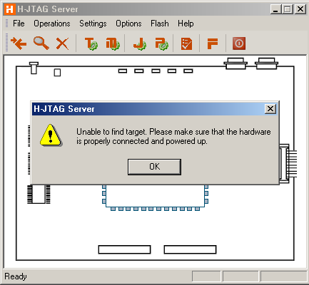
- Run the H-JTAG server. The install process should have placed an H-JTAG icon
on your desktop.
- If H-JTAG complains that it can't find your target, you may need to
reconfigure it.
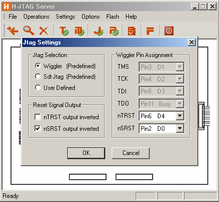
We don't have a Macraigor pod, but with the Olimex pod, you will
need to change the JTAG settings in H-JTAG.EXE. Select "Settings" from the menu,
then "JTAG settings".
As shown in the screen-shot below, TMS, TCK,TDI, and TDO are all preset correctly if
you select Wiggler as the hardware device. However nTRST must be set to "Pin6 D4",
and "nTRST Output Inverted" must not be checked.
nSRST can be set to "NO SYS RST", or nSRST can be set to "Pin2 D0" with "nSRST
Output Inverted" checked.
- Once H-JTAG is up and running, you can run NoICE
Running NoICE
- Run NoICE.
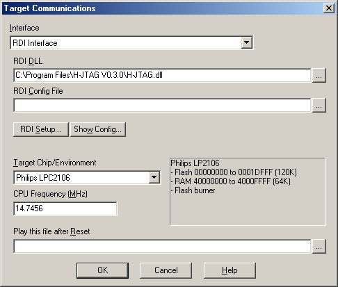
- Select "Target Communications" from the "Options" menu, then
select "RDI Interface" from the "Interface" drop-list.
- Type or browse to the RDI DLL provided by your RDI implementation.
If you are using the H-JTAG Interface, this will usually be
something like
C:\Program Files\H-JTAG V0.3.0\H-JTAG.dll
- Select your Target Chip: "Philips LPC2106" in this example.
- Set the CPU frequency to match the target. The Olimex board has an 14.7456 MHz crystal,
so the CPU frequency is 14.7456 MHz.
- For now, leave "Play this file after Reset" blank.
- More information is available about
configuring NoICE's RDI interface.
Press "OK" in the Target Communications dialog, and NoICE will show an initial
display like that shown below. If you exit NoICE and come back in, you will
return right here.
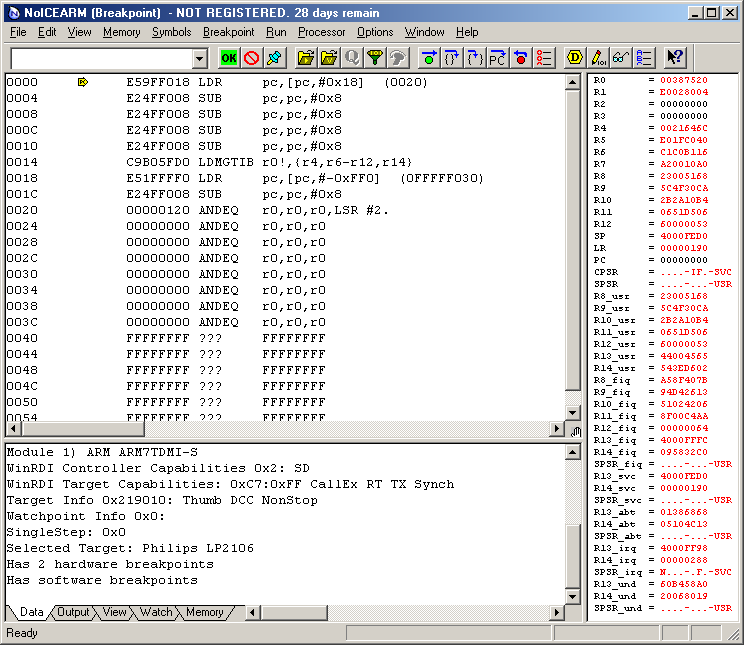
In this case, memory contains a previously-burned program. Since the
ARM begins execution at address 0, that is where PC starts out. NoICE
disassembles from the PC.
At this point, you may wish to repeat the simulator examples
on real hardware.
The next step is to burn a program into Flash. This example uses
ImageCraft ICCARM,
as described in the previous section of the tutorial, Compiling for Source-level Debugging.
You can follow along even if you don't have this compiler. All files necessary for
you to run the NoICE demo may be downloaded here: hellofoo.zip.
Setup for other compilers is generally similar.
|
Run NoICE. Select "File", "Load...".
By default, you will see hex files such as hellofoo.s19. You could load that, but
all you would get would be disassembly, as the s19 file doesn't contain any symbolic
debug information.
So change the "Files of type" to"ImageCraft DBG files".
Navigate to hellofoo.dbg and press "OK".
NoICE help on LOAD
|
 |
|
When you Load the file into the Flash range, a progress dialog appears:
It shows the address being burned and the progress of the burn.
|
 |
Once burning is completed, you can continue with the
source-level debugging example
NoICE help
NoICE help on ARM
|