 |
|
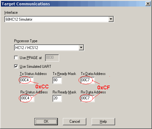
HC12: Running NoICE for the First TimeIn most cases, you will be debugging programs at source level, using symbols rather than addresses. However, as an introduction to NoICE we recommend that you get some experience with the user interface first. The first time you run NoICE after installing it, a dialog will appear asking you to choose a method of communications. For this section of the tutorial, we select "Simulator". (Some NoICE target processors, such as Z80 and 6502, do not have a simulator option. For these, you may wish to select "Dummy Target". This will let you use many NoICE commands, but will not allow you to execute programs.)
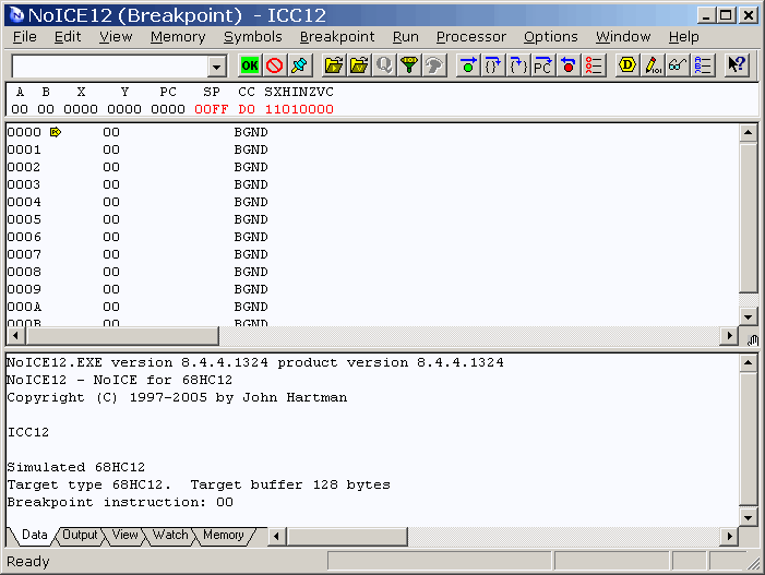
By default, the simulator places the UART at the addresses appropriate for most non-S 68HC12 parts, such as the A4, DT128 etc. Our example will be for a MC9S12DP256, using SCI0 as the serial port, so these are not the correct addresses. Consulting the datasheet for the MC9S12DP256, we find that SCI0 status register SCISR1 is at address 0xCC and data register SCIDRL is at address 0xCF. Change the addresses as indicated. The TxReady and RxReady masks are correct as is, since the SCI register layout is the same regardless of the location of the SCI. The UART address is important during simulation only insofar as you will need to make sure that you compile for the correct target in a later section of the tutorial. Don't worry, we will remind you. Press "OK" in the Target Communications dialog, and NoICE will show an initial
display like that shown below. If you exit NoICE and come back in, you will
return right here.
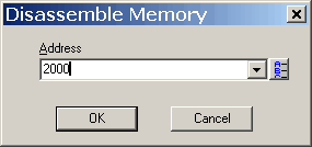
Unlike a real 68HC12, the simulator initializes all memory to zeros. Since the reset vector contains 0000, that is where PC starts out. NoICE disassembles from the PC, showing a bunch of BGND instructions - op-code zero. When NoICE starts up, it will disassemble instructions beginning at the initial PC address. If you are using the serial monitor, PC will be set to whatever value the monitor sets it to. If you are using BDM or one of the other built-in interfaces, PC may be set to the contents of the reset vector, or it may contain a garbage value. You can disassemble at any address by selecting View, Disassemble At..., and entering an address. Or use the "U" command in the command edit box in the NoICE toolbar. To continue disassembly, just click in the disassembly window and press the PageDown key. Memory Edit: Click on the "Memory" tab near the bottom of the NoICE screen.
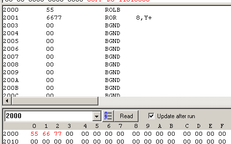
Enter the address 2000 and press the "Read" button or the Enter key.
NoICE will show the contents of memory in hex and ASCII. To change the contents of memory, click on a byte and type hex characters: 55, 66, 77 in the screenshot above. Changed bytes are shown in red. To edit the ASCII, click on a character in the ASCII field and type the desired characters. Values are written to the target as you change each byte. Note that the memory window may not be suitable for use on I/O addresses, as extra reads and writes of I/O locations may cause undesired actions. In addition to the Memory tab, you can edit memory using the EDIT, IN, and OUT commands. EDIT is most useful in conjunction with symbols and datatypes. IN and OUT are designed for access to I/O devices. Disassembly: We can view our changes to memory in the disassembly window by either
Either way, the result is some not very useful instructions
Mini-assembler:
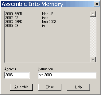
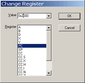
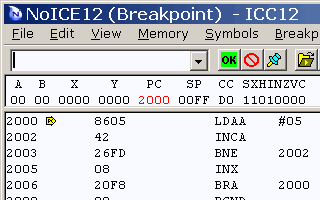
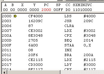
Use the disassembly feature to see the results of your handiwork. Registers:
Single-step:
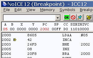
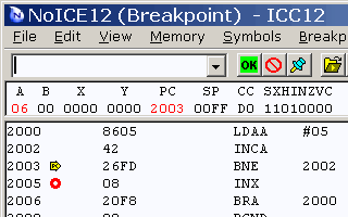
Press F11 again. PC changes to 2003, and A increments to 6. You can continue stepping around the loop until you get bored. Breakpoints:
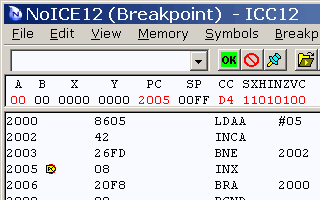
Press F5 or click Go again. The program again stops at the breakpoint, but X has incremented. Remove the breakpoint by double-clicking on address 2005. Press F5 or click Go to let the program run free.
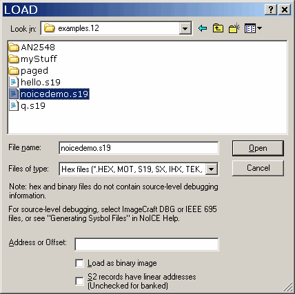
Loading a hex File:
Continue the tutorial with Compiling for Debugging Continue the tutorial with Connecting to hardware |
